PTP - Precision Time Protocol
IEEE 1588 V1 and V2 PTP Boundary clock capabilities in Industrial Managed Switches
To synchronize distributed clocks throughout a Local Area Network (LAN), Network Time Protocol (NTP) and Simple Network Time Protocol (SNTP) are popular methods that are accurate to the millisecond range. However, for industrial networks, clock synchronization requires much greater precision.
The IEEE 1588 standard for Precision Time Protocol (PTP), which was first adopted in 2002 for Automation and Measurement applications, provides a method for clock synchronization with microsecond accuracy. PTP was also adopted under the IEC 61588 standard in 2004. Version 2 of the IEEE 1588 standard was ratified in 2008 to address telecommunications and audio-video bridging applications.
PTP is in demand wherever processes need to be synchronized exactly, such as automation and control systems, measurement and automatic test systems, power generation, transmission and distribution systems as well as telecommunications.
How Does PTP Work?
A simple solution to synchronize clocks on an Ethernet network might be to simply send a message with the value of the time of the master clock to the slaves. Upon receipt of the message, the slaves would simply reset their own clocks to match the master clock value. However, because of the time it takes to send the message due to propagation delays in the Ethernet path, as well as delays introduced by processor queuing, IP message creation and latency, the actual time the message is received by the slave no longer accurately represents the time specified by the master. PTP addresses these affects through the use of protocol messages sent between various PTP nodes to determine the clock offsets and delays inherent in the network.
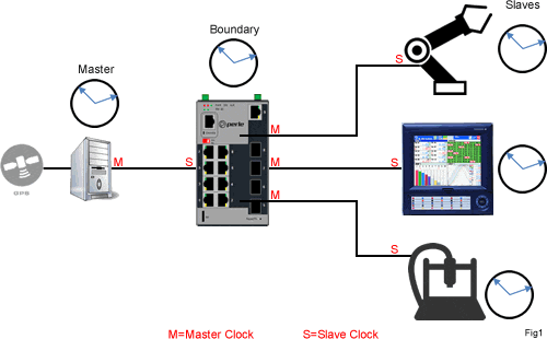
PTP has two types of clocks, masters and slaves. A clock in a terminating device is a slave. A master, ideally controlled by an external radio clock or a GPS receiver, synchronizes the respective slaves connected to it. In a network you will also have transmission components, like an Ethernet Switch, with a boundary clock. The boundary clock operates as a slave to the master clock, and then switches to operate as a master clock to the terminating slave devices. Each slave is synchronized to the time, frequency and phase of the master clock and, by extension, synchronized to all other slave nodes.

The synchronization process is divided into two phases. First, obtaining a clock offset correction and then a determining the delay measurement.
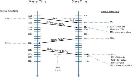
To illustrate, the diagram below shows the steps taken to synchronize the slave clock to that of the master. In this example, the slave clock starts with an offset ( difference ) from the master of 20 seconds ( IE master at 100 seconds and slave at 80 ). Note that the time values used in this example do not represent actual network performance, but are used to simplify the explanation.

The master constructs a Sync message at 100s to send to the slave. However, due to internal queuing and latencies, the message is actually sent and timestamped internally at 101s local master time. Due to delays in the network the slave receives the Sync message two seconds later at 83s.
A Follow-up message is sent shortly after by the master at 103s. This follow up message contains the previously timestamped value of 101s in the message. This follow-up message is received two seconds later at 85s local slave time. The slave then takes the 101s time in the message and subtracts the previously timestamped value of 83s, resulting in a calculated offset of 18 seconds. The offset is then added to the present time resulting in a new clock time of 103 seconds. However, the Master and Slave are not yet completely in sync. This new adjustment has not accounted for the delay in the network.
The second phase determines the network delay. The slave sends out a Delay Request message to the master at 108s. The master receives and stores this message at 112s local master time. A Delay Reply message is sent back to the slave with the time (112s) that the Delay Request message was received. The slave receives the Delay Reply at 115s local slave time. The slave can now determine the network delay by subtracting the time it sent the Delay Request ( 108s ) from the time the master received the Delay Request ( 112s ), resulting in a value of 4 seconds. However, because two messages were sent, the result is divided by 2, a two second delay. The slave then adjusts its clock by 2 seconds ( 117s ) and is now perfectly in sync with the master.
The internal real time clocks of the various devices will inevitably drift over time. To compensate for this, the master clock will periodically perform the poll sequence to the slaves to maintain their accuracy with the master clock.
When using switches between a master clock and slaves, run time variations that occur in switches lead to inaccuracies in messages sent between the master and slaves. Given that switches save the received data packets completely, and queue effects can considerably delay the transmission under certain circumstances, great fluctuations may occur here. At low network load, this may have little effect, but during times of greater network load, this can considerably affect the synchronization accuracy.
This is resolved by using Ethernet switches with IEEE 1588 PTP Boundary clock capabilities. These contain their own PTP instance where they operate as a PTP slave and are synchronized in relation to the connected master clock. For the downstream PTP slaves, every switch port then operates as a PTP master and synchronizes the slaves with its internal time. This compensates all run time fluctuations and wait times in the switches and enables maximum accuracy to be achieved even through larger Ethernet networks.
IEEE 1588 V1 and V2 PTP Boundary clock capabilities are available in Perle Industrial Managed Switches with the PRO software feature set.
